


Introduction and Gross Anatomy:
The retinal and choroidal circulatory system can be visualized in vivo in the presence of normal media clarity. Many important diseases of the retina are related to or associated with the changes in the vasculature of the retina and/or choroid. Hence, it is important to understand the circulatory systems involved to better recognize disease states of the posterior segment.
The retinal and choroidal vascular anatomy can be basically divided into 3 parts:
- Retinal and choroidal vasculature
- Superficial and deep capillary plexus
- Inner and outer blood-retinal barriers
A: Retinal and Choroidal Vasculature:
The retina receives its nutrition from two discrete circulatory systems—the retinal and the choroidal blood vessels. Both are derived from the ophthalmic artery, which is the first branch of the internal carotid artery.
The major branches of the ophthalmic artery are the posterior ciliary arteries, the central retinal artery, and the muscular branches. [1] The posterior ciliary arteries branch out proximal to the central retinal artery. This explains the early filling of the dye in the choroidal circulation (≈1-2 sec prior) in comparison to the retinal circulation. The choroid receives its blood supply via the posterior ciliary arteries. Two posterior ciliary arteries exist—a medial and a lateral. [2] The choroidal watershed area, which represents the area between the supply of each posterior ciliary artery, is usually a vertically oriented zone situated between the optic disc and macula. The posterior ciliary arteries further divide into two long posterior ciliary arteries and numerous short posterior ciliary arteries. The posterior choriocapillaris is supplied by these short posterior ciliary arteries, which enter the choroid in the peripapillary and submacular region. The outer choroid, known as Haller’s layer, is composed of large caliber, non-fenestrated, vessels. The inner choroid is referred to as Satler’s layer and is composed of significantly smaller vessels. The choriocapillaries of the innermost choroid. The choroid supplies the outer retina with nutrients and maintains the temperature and volume of the eye. The choroidal circulation, which accounts for 85% of the total blood flow in the eye, is a high-flow system with relatively low oxygen content.
The choroid is drained through the vortex venous system, which usually has between four and seven (usually six) major vessels, one or two in each quadrant, located at the equator. The vortex veins drain into the superior and inferior orbital veins, which drain into the cavernous sinus and pterygoid plexus, respectively. Collateralization between the superior and inferior orbital veins usually exists. The central retinal vein drains the retina and the prelaminar aspect of the optic nerve into the cavernous sinus. Thus, both the retinal and choroidal circulatory systems are in communication with the cavernous sinus.
The central retinal artery provides nourishment for the inner retinal layers. The outer retinal layers are avascular and are supplied by diffusion from the choriocapillaris. Despite this dual circulation to the retina, functionally little overlap occurs, with the watershed zone at the outer plexiform layer. The retinal arteries and arterioles remain in the inner retina, and only capillaries are found as deep as the inner nuclear layer. The retinal venous drainage of the retina generally follows the arterial supply. The retinal veins (mainly venules) are present in the inner retina, where they occasionally interdigitate with their associated arteries. The retinal veins carry off the waste products from the retina.
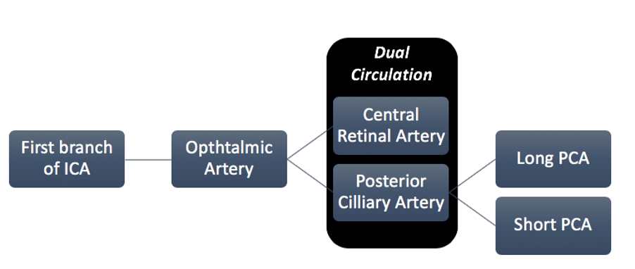
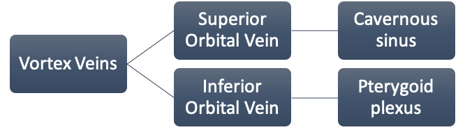
Fig.1 Retinal and Choroidal Vasculature (Abbreviations: (ICA – Internal Carotid Artery, PCA – Posterior Ciliary Artery)
B: Capillary plexus:
These retinal capillaries form an interconnecting two-layer network. The first layer is located in the nerve fiber and ganglion cell layer known as the superficial capillary plexus and the second lies deeper, in the inner nuclear layer and outer plexiform layer known as the deep capillary plexus.
In the peripapillary area an additional capillary network lies in the superficial portion of the nerve fiber layer, constituting the radial peripapillary capillaries distributed around the optic disk and along the temporal superior and inferior retinal vessels.
The choriocapillaris are distributed as a dense network of one layer of freely connected capillaries in the peripapaillary and submacular area. The choriocapillaris have multiple fenestrations allowing the unbound dye to leak through it. This is responsible for the diffuse background fundus fluorescence, also known as the “choroidal flush” on FFA. Venous drainage from the choriocapillaris is primarily through the four vortex veins. Minor drainage also occurs through the ciliary body and the anterior ciliary vein. [3]
C: Blood Retinal Barrier:
The BRB consists of inner and outer components (inner BRB (iBRB) and outer BRB (oBRB)) and plays by itself a fundamental role in maintaining the microenvironment of the retina and retinal neurons. The presence of tight junctions (zonulae occludentes) between neighboring retinal endothelial cells at the inner BRB and between retinal pigment epithelial cells at the outer BRB is particularly relevant for the barrier function. Fluorescein angiography, permits a dynamic evaluation of local circulatory disturbances and identifies the sites of BRB breakdown. [4]
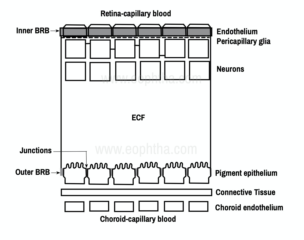
Fig.2 Inner and Outer Blood Retinal Barrier (Picture recreated from Quillen D,Blodi B, (2002).Clinical Retina )
Principle of Fluorescein Angiography:
Fluorescein angiography is a diagnostic technique that allows the sequential visualization of blood flow simultaneously through retinal, choroidal, and iris tissues as the fluorescein dye is injected into the bloodstream via the vein in the arm. FA is based on the principle of fluorescence. Fluorescence is the luminescence that is maintained only by continuous excitation i.e. excitation at one wavelength occurs and is emitted immediately through a longer wavelength. The dye absorbs light in the blue range of the visible spectrum peaking at 465-490nm and emits light of theyellow-green range of visible spectrum peaking at 520-530nm. This is the fundamental principle of FA. [5]
Pseudo fluorescence: It occurs when nonfluorescent light passes through the entire filter system. If green–yellow light penetrates the original blue filter, it will pass through the entire system. If blue light reflected from nonfluorescent fundus structures penetrates the green–yellow filter, pseudo fluorescence occurs.
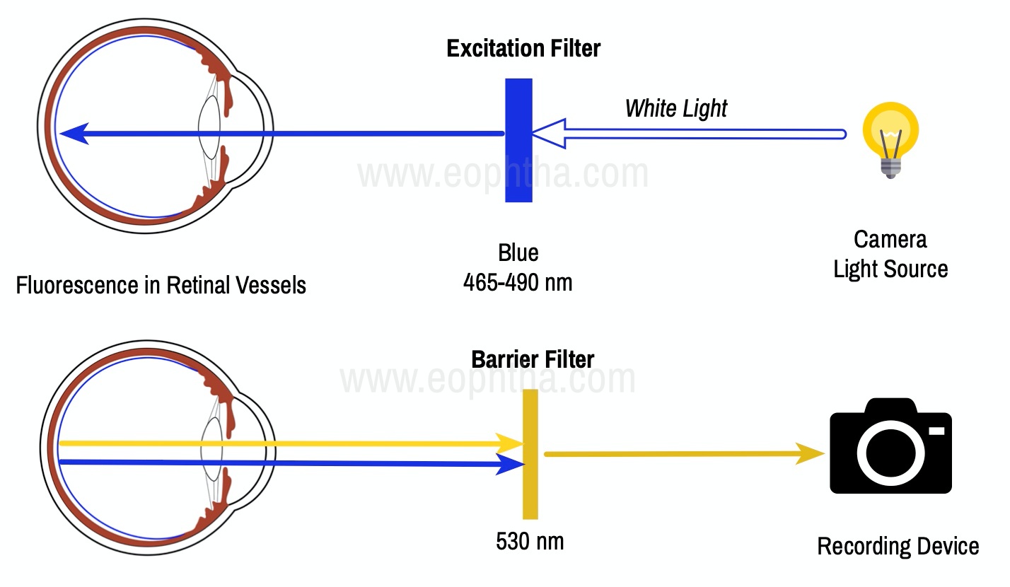
Fig.3 Principles of Fluorescein Angiography:
Equipment and Technique
1. Camera and Auxiliary Equipment: In clinical retinal practice, cameras ranging from 35° to 200° are routinely used. Regardless of range, a camera with the ability to yield high resolutions of the posterior pole is essential for most macular problems especially when laser treatment is to be done, as with background diabetic retinopathy, branch vein occlusion, or choroidal neovascularization.
2. Fluorescein Solution: Fluorescein (sodium fluorescein) is an orange water-soluble dye and has a low molecular weight (376.27 Da), and when injected intravenously, remains largely intravascular (>70% bound to serum proteins). It is excreted in the urine over 24–36 hours. It readily diffuses through most of the body fluids and through the choriocapillaris, but it does not diffuse through the retinal vascular endothelium or the pigment epithelium
3. Matched Fluorescein Filters: Cobalt blue excitation filter. Incident white light from the camera is filtered so that blue light enters the eye, exciting the fluorescein molecules in the retinal and choroidal circulations. Yellow-green barrier filter blocks any blue light reflected from the eye, allowing only yellow-green emitted light to pass.
4. Injecting the Fluorescein: A syringe with a 23-gauge winged infusion set, or scalp-vein needle is used for injection. Injection of the fluorescein is coordinated with the photographic process and is done after the first photographs have been taken. When ready, the photographer will signal the physician. Rapid injection of 2 or 3 seconds delivers a high concentration of fluorescein (5ml of 10%) to the bloodstream in a short time and yields somewhat better photographs than a slower injection. For this reason, a slower injection (4–6 seconds) is preferable; the photographs will still be of good quality. Because some fluorescein dye remains in the tubing, the scalp-vein needle should have short, rather than long, tubing to ensure that more of the dye is injected. [6]
Normal Fluorescein Angiography:
The angiogram consists of the following overlapping phases:
- The choroidal (pre-arterial) phase typically occurs 9–15 seconds after dye injection – longer in patients with poor general circulation – and is characterized by patchy lobular filling of the choroid due to leakage of free fluorescein from the fenestrated choriocapillaris. A cilioretinal artery, if present, will fill at this time because it is derived from the posterior ciliary circulation.
- The arterial phase starts about a second after the onset of choroidal fluorescence, and shows retinal arteriolar filling and the continuation of choroidal filling
- The arteriovenous (capillary) phase shows complete filling of the arteries and capillaries with early laminar flow in the veins in which the dye appears to line the venous wall leaving an axial hypo fluorescent strip. This phenomenon reflects initial drainage from posterior pole capillaries filling the venous margins, as well as the small vessel velocity profile, with faster plasma flow adjacent to vessel walls where cellular concentration is lower.
- The venous phase. Laminar venous flow progresses to complete filling, with late venous phase featuring reducing arterial fluorescence. Maximal perifoveal capillary filling is reached at around 20–25 seconds in patients with normal cardiovascular function, and the first pass of fluorescein circulation is generally completed by approximately 30 seconds.
- The late (recirculation) phase demonstrates the effects of continuous recirculation, dilution, and elimination of the dye. With each succeeding wave, the intensity of fluorescence becomes weaker although the disc shows staining. Fluorescein is absent from the retinal vasculature after about 10 minutes. [7][8][9] [10]
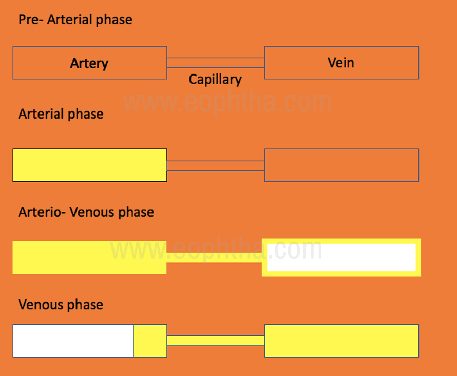
Fig.4 Phases of Fluorescein Angiogram
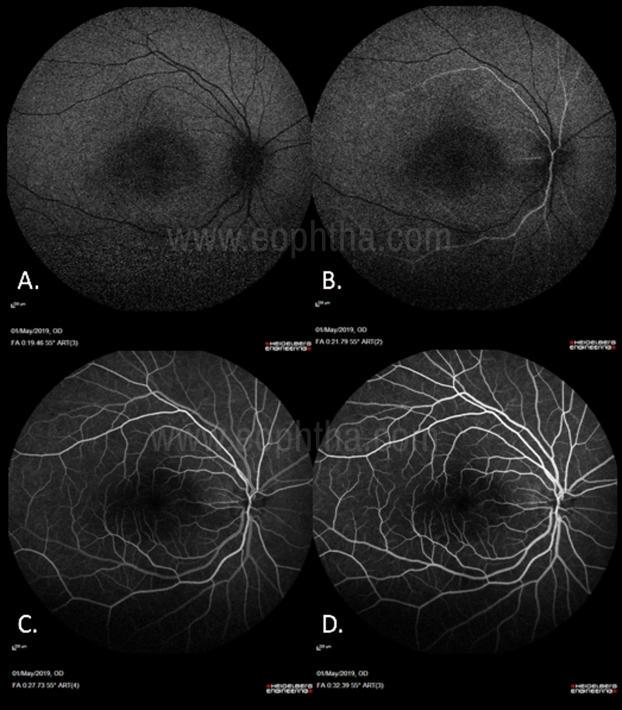
Fig.5 Phases of Normal Angiogram(Fig 5.A: Pre-Arterial Phase: No arterial filling, Choroidal flush seen along with filling of the cilioretinal artery. Fig 5.B: Arterial Phase: Filling up of the arteries. Fig 5.C: Arterio-Venous phase: Arteries have been filled up along with capillaries and start of laminar flow in veins. Fig 5.D: Laminar venous flow progresses to complete filling, with late venous phase featuring reducing arterial fluorescence.)
|
Phases of angiogram |
Time (in seconds) |
|
Injection |
0 |
|
Posterior ciliary artery |
9.5 |
|
Choroidal phase |
10 |
|
Arterial |
10 - 12 |
|
Arteriovenous |
13 |
|
Early venous |
14 – 15 |
|
Mid venous |
16 -17 |
|
Late venous |
18 – 20 |
|
Late (elimination) |
>5 minutes |
Table. 1 Phase of Angiogram and its Timeline
Appearance of the foveal avascular zone (FAZ):
The dark appearance of the fovea is caused by three factors: a) absence of blood vessels in the FAZ; b) blockage of background choroidal fluorescence due to the high density of xanthophyll at the fovea and c) blockage of background choroidal fluorescence by the RPE cells at the fovea, which are larger and contain more melanin and lipofuscin than elsewhere in the retina. In macular ischemia, there is distortion and enlargement of the FAZ.
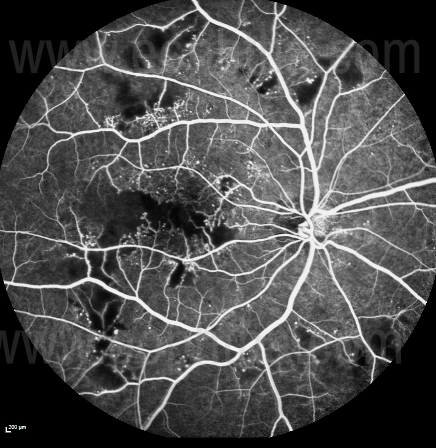
Fig. 6 Macular Ischemia on FFA seen in a patient with diabetic retinopathy:
Abnormal fluorescence patterns on fluorescein angiography:
Interpretation of the fluorescein angiogram follows a simple and logical progression. The first step is to recognize areas of abnormal fluorescence and determine if they are hypo fluorescent or hyperfluorescent.
Hyperfluorescence:
Hyperfluorescence is any abnormally light area on the positive print of an angiogram, that is, an area showing fluorescence in excess of what would be expected on a normal angiogram. Hyperfluoroscence can be noted in the absence of dye injection (autofluorescence and pseudo fluorescence) or after dye injection (true hyperfluoroscence). Autofluorescence is an inherent property of a lesion to spontaneously fluoresce even in the absence of dye. Pseudo fluorescence occurs when nonfluorescent light passes through the entire filter system. If green-yellow light penetrates the original blue filter, it will pass through the entire system. If blue light reflected from nonfluorescent fundus structures penetrates the green-yellow filter. Basically, the pseudo fluorescence occurs due to the mismatch filters.
There are four possible causes of abnormal true hyperfluorescence: (1) Transmitted fluorescence; (2) Staining (3) Pooling and (4) Leakage. [9] [10]
A) Transmitted hyperfluorescence (Window defects): This is a type of early hyperfluorescence due to RPE atrophy. In this type of hyperfluoroscence, there is increased visualization of the normal choroidal fluorescence due to the defects/atrophy of the overlying RPE. There is increased early hyperfluoroscence which fades during the late stages of the angiogram Figure 7.
B) Staining: This is a type of late hyperfluoroscence which occurs due to the retention of the dye by the tissue e.g. disciform scar.
C) Pooling: In this type of hyperfluoroscence, there is an accumulation of the dye in a closed space e.g. cystoid macular edema and retinal pigment epithelial detachment.
D) Leakage: This type of hyperfluoroscence occurs due to the leakage of the dye into an open space e.g. NVE (where the dye leaks into the preretinal space), CSCR leak (where the dye leaks into the subretinal space) and choroidal neovascular membrane (where the dye leaks into the sub-RPE or subretinal space).
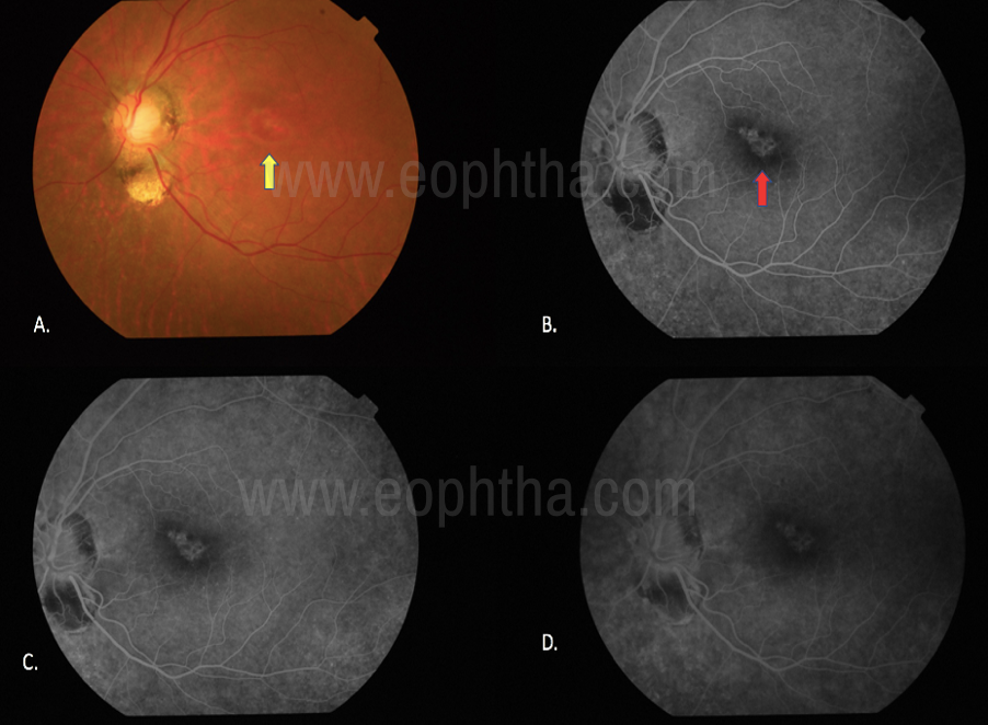
Figure 7: Transmission defect: 7.A. Transmission defect (window defect) in a case with focal RPE loss, Colour fundus photograph shows the bright reddish-orange underlying choroidal vasculature (yellow arrow). Fig 7.B. Early phases of FFA shows the hyperfluroscence in the area of RPE loss due to increased visualization of the normal choroidal fluorescence (red arrow). Fig 7.C, D. On Late phases the window defects remain uniform in size throughout the angiogram and only their brightness falls with the choroidal fluorescence.
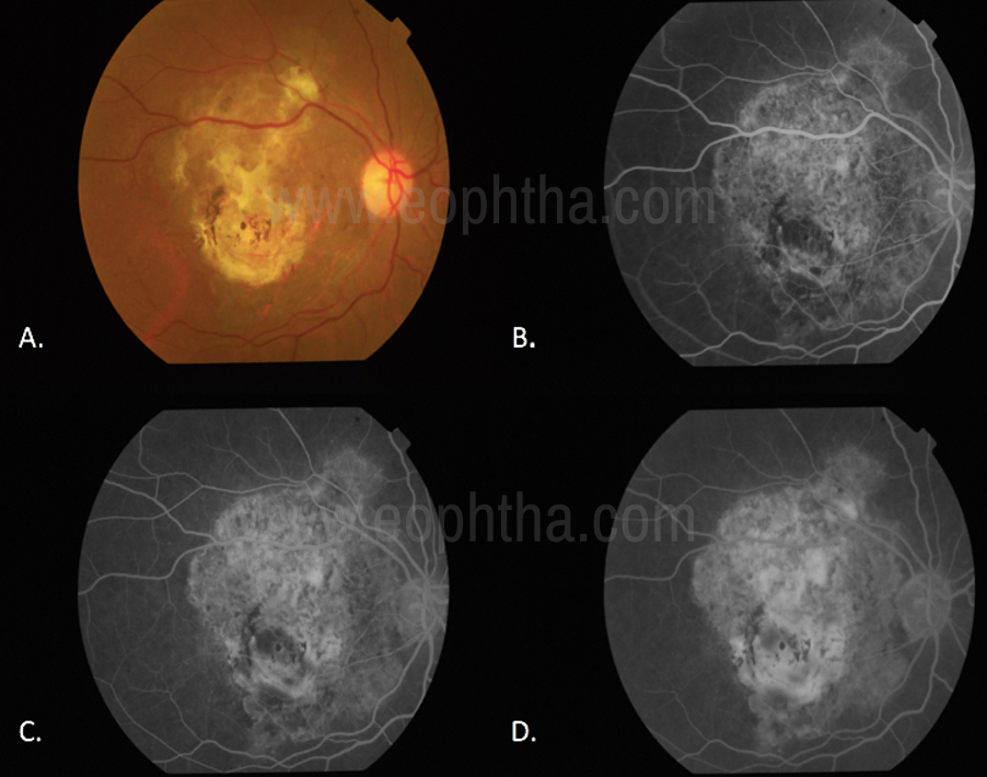
Figure 8. Staining (8.A. Disciform scar in the right eye on color fundus photography. Fig 8.B-D.Staining of the Disciform scar through various phases of the angiogram.)
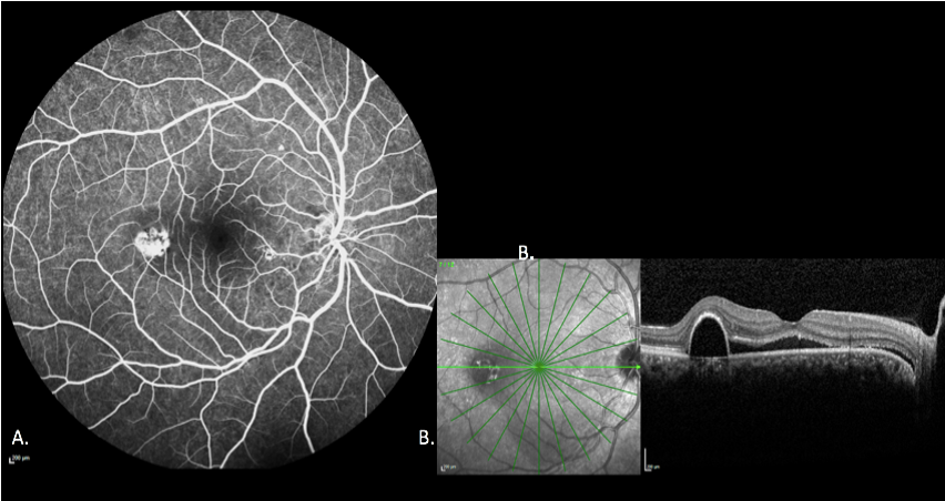
Figure 9 Pooling9A-B: In a case of CSR and serous PED as the fluorescein escapes into the PED, the margins of the space trap the fluorescein there is an increase in intensity but the size of the lesion remains the same in the different phases of the angiogram.
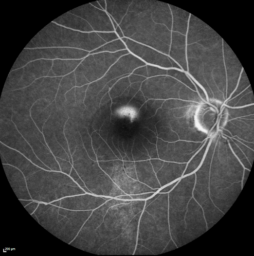
Figure 10 Leakage from a CSCR leak: A smokestack leak in a case of acute CSCR
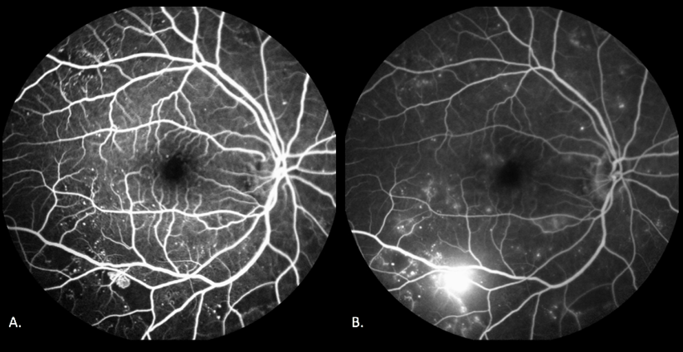
Figure 11 Leakage from an NVE
In a case of Proliferative Diabetic Retinopathy – Neovascularisation elsewhere can be seen along the inferior arcade which appears hyperfluorescent in early images (Fig 11.A) but increases in shape and size as the angiogram progresses (Fig 11.B)
Hypo fluorescence:
Hypo fluorescence is any abnormally dark area on the positive print of an angiogram. The key to differentiating blocked fluorescence from a vascular filling defect is to correlate the hypofluroscence on the angiogram with the ophthalmoscopic view. If there is material visible ophthalmoscopically that corresponds in size, shape, and location to the hypofluroscence on the angiogram, then blocked fluorescence is present. If there is no corresponding material on the colour photograph, then it must be assumed that fluorescein has not perfused the vessels and that the hypofluroscence is caused by a vascular filling defect.
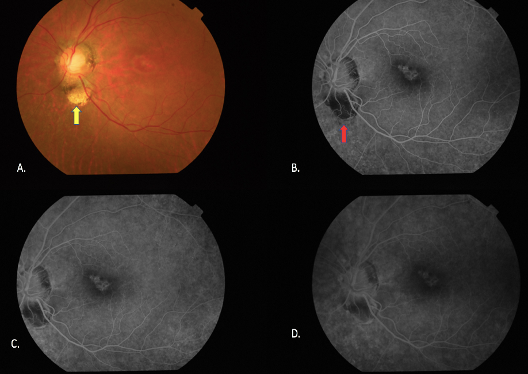
Figure 12: Filling Defect(In a case of choroidal coloboma – the absence of vasculature in the colobomatous area on color fundus photographs can be seen (yellow arrow, Fig. 12.A) On FA, Hypofluroscence is noted in the corresponding area due to lack of vasculature (Red arrow, Fig. 12.B, C, D)
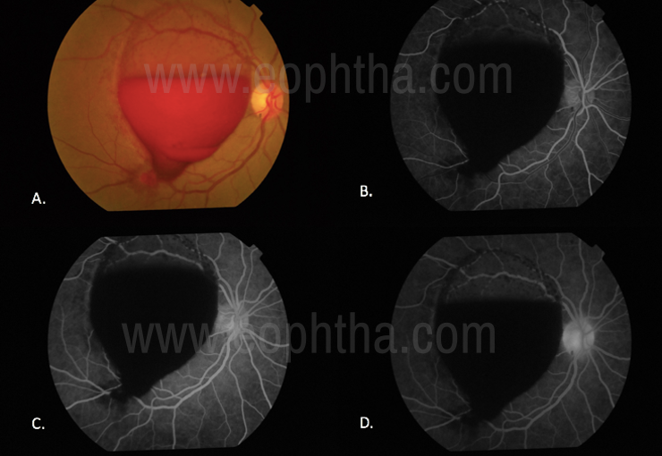
Figure 13 Blocked Fluorescencedue to the presence of Pre-Retinal Haemorrhage there is blocking of underlying fluorescence
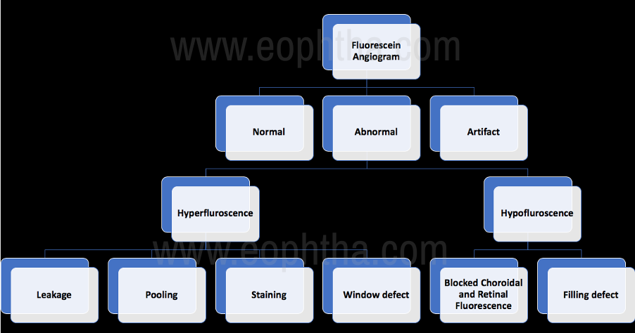
Figure 14: Interpretation of Abnormal Fluorescein Angiography:
Indocyanine Green Angiography (ICGA)
ICGA is also based on the principle of fluorescence. The dye absorbs light in the infrared spectrum 790-805nm and peaks at 835 nm. Indocyanine green (ICG) has several advantages over sodium fluorescein in imaging the choroidal vasculature. Its physical characteristics allow for visualization of the dye through overlying melanin, xanthophyll pigment, serosanguineous fluid, or lipid exudates. [11]
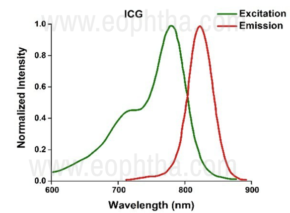
Figure 15 The absorption and emission spectrum of ICG Dye
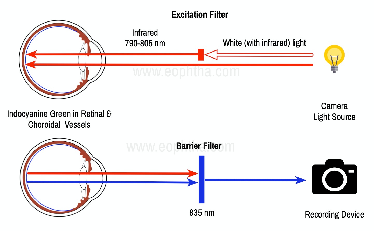
Figure 16 Principle of ICG Angiography
Equipment and Technique
1. There are several instruments at present that can be used to perform ICGA. All of them can be divided into two main categories:
- Digital flash fundus cameras
- Confocal Scanning Laser Ophthalmoscopes (CSLO’s)
2.Indocyanine Green Dye: ICG is a tricarbocyanine, anionic dye. ICG absorbs light in the near-infrared region of the spectrum. The maximum absorption is at 790 nm, while the maximum emission occurs at approximately 835 nm. These optical properties allow penetration through macular pigment, melanin blood, and pigment. About 98% of ICG is bound to plasma protein, in particular to globulins, such as A1-lipoproteins. In pig plasma, lipoprotein HDL3 is the major binding protein. ICG is excreted by the liver with negligible extrahepatic removal
3. Matched Fluorescein Filters: ICG fluorescence is only 1/25th that of fluorescein so modern digital ICGA uses high-sensitivity video angiographic image capture by means of an appropriately adapted camera. Both the excitation (805 nm) and emission (835 nm) filters are set at infrared wavelengths. Alternatively, scanning laser ophthalmoscopy (SLO) systems provide high contrast images, with less scattering of light and fast image acquisition rates facilitating high-quality ICG video.
4. Injecting Indocyanine Green Dye: For SLOs the standard dosage is 25 mg of ICG dissolved in 3 mL, and 1 mL of the solution is injected. Intravenous ICG injection should be rapid and immediately followed by a 5-mL saline flush. [12]
Normal Indocyanine Green Angiography:
The angiogram consists of the following overlapping phases:
Early Phase (< 1min): It is correlated with the filling of different layers of the choroid. The first choroidal vessels to be filled are the ones of the deeper Haller’s layer, followed by the intermediate Sattler’s layer. The choriocapillaris is the last layer to be filled (therefore the sequence progresses from the biggest and outermost to the smallest and innermost vessels).
Early Mid Phase (1-3 mins): Shows greater prominence of choroidal veins as well as retinal vessels.
Late Mid Phase (3-15 mins): Shows fading of choroidal vessels but retinal vessels are still visible; diffuse tissue staining is also present
Late Phase (15-45 mins): Choroidal vortex veins are visible in the late phase of ICGA.
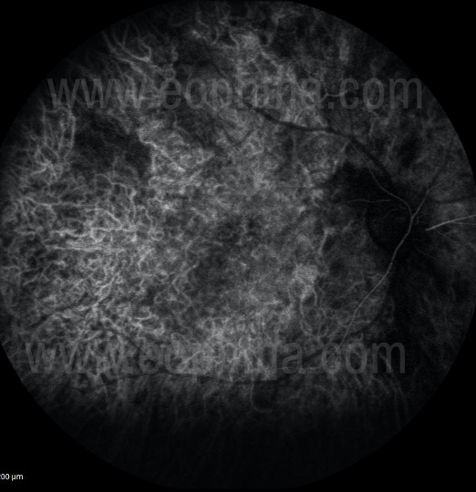
Figure 17 Early phase of ICGa (In Early phases of ICGa there is disc hypofluroscence seen along with rapid filling of choroidal arteries and choriocapillaris. There’s an early filling of choroidal veins and retinal blood vessels are not filled. The watershed zone is also not filled at this stage.)
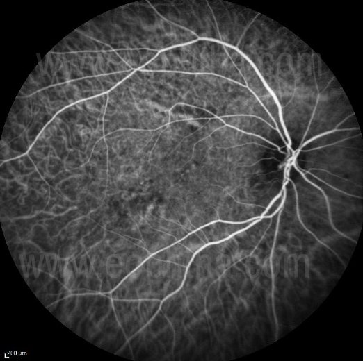
Figure 18 Mid Early phase of ICGa:(In Mid Early phases of ICGa there is fading of choroidal arterial filling and a prominence of choroidal veins. There is a Filling of retinal arteries and veins. The watershed zone is filled at this stage.)
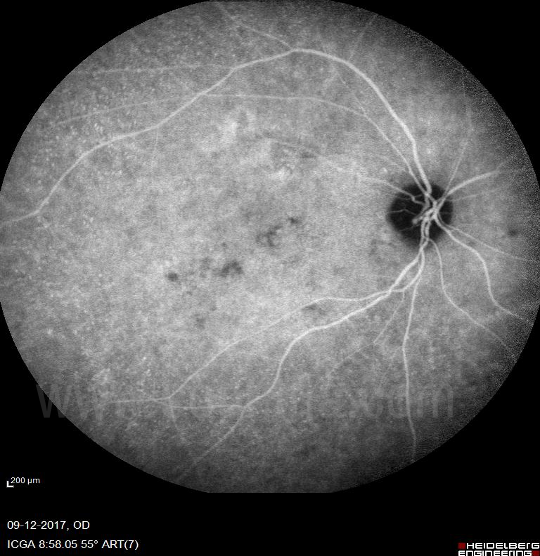
Figure 19 Middle-Late of ICGa (In mid-late phases of ICGa there is reduced filling of choroidal vessels and diffuse hyperfluroscence due to diffusion of dye from choriocapillaris. There is the persistent filling of retinal vessels.)
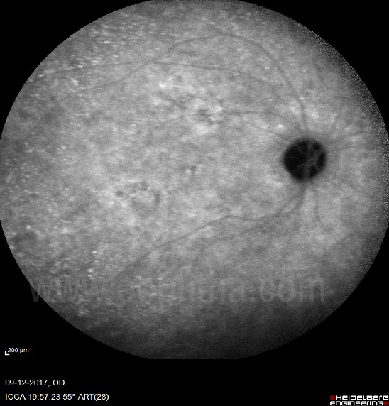
Figure 20 Elimination phase of ICGa (In the elimination phase of ICGa the large choroidal and retinal vessels empty up and there is a presence of diffuse hypofluroscent background.)
Role of ICGA in choroidal disorders:
Abnormal hyperfluoroscence areas on ICGA are called hot spots. There are 2 types of hot spots:
1) Plaques are usually formed by late-staining vessels and usually correspond to occult CNV. They are > 1 DD in size.
2) Focal hot spots are well-delineated fluorescent spots < 1DD in size that typically indicates retinal angiomatous proliferation (RAP) and polypoidal vasculopathy
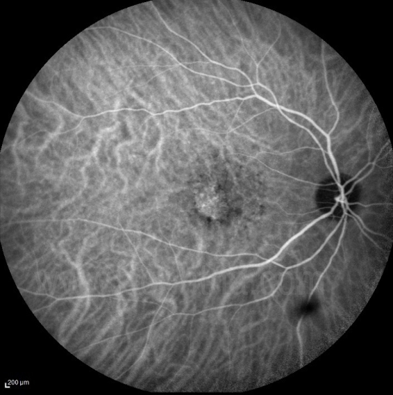
Figure 21 Occult CNVM on ICGa(Late phase of ICGa showing the staining of the abnormal choroidal vessels in Occult CNVM)
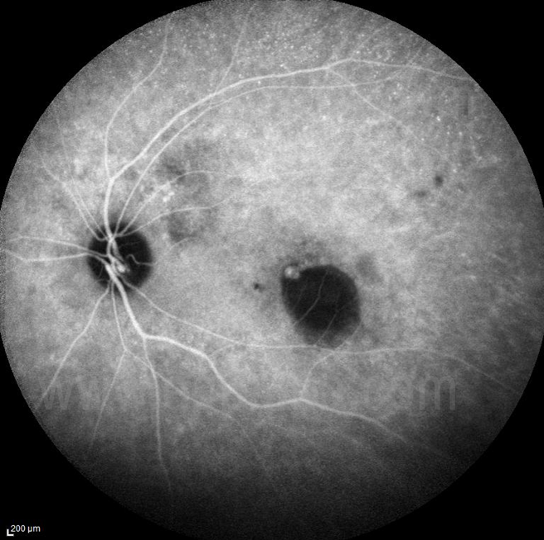
Figure 22 PCV – Polyp on ICGa
Role of ICGA in PCV:
- Identify polyps
- Differentiate CNVM from IPCV
- Look for polyp regression post treatment
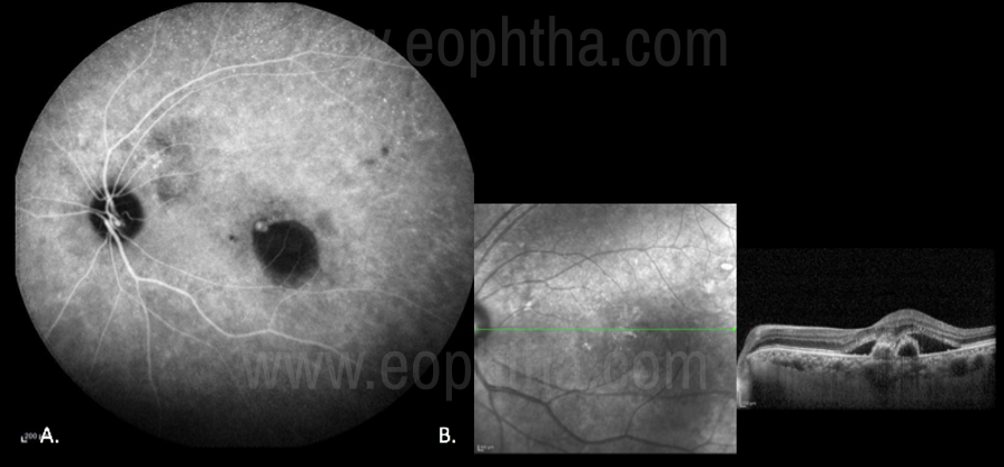
Fig 23 Role of ICGa in PCV(A case of PCV, Late phase of ICGa showing a focal hot spot suggestive of a Polyp. Fig 23.A. OCT image showing fibrovascular PED and SRF. Fig 23.B.)
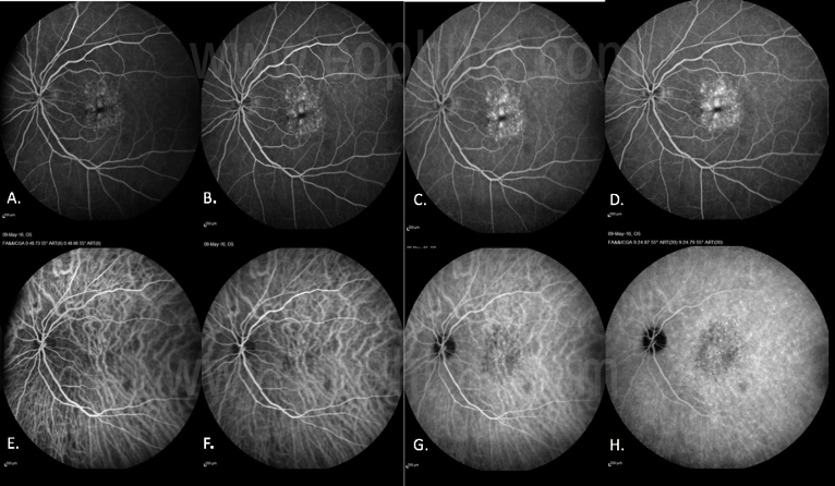
Fig 24 Role of ICGA in AMDTo differentiate between Type 1 AMD CNVM and IPCV with BVN
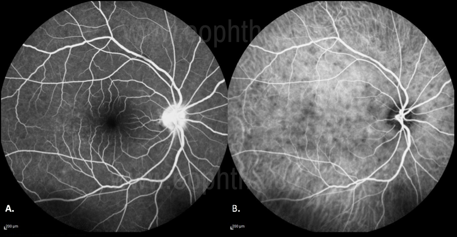
Figure 25 ICGA in VKH
Identify the incipient stage of the disease: ICGA signs of acute VKH disease have been clearly standardized with four signs consistently present. These include disc hyperfluorescence on FA (Fig 25. A) early choroidal vessel hyperfluorescence, intermediate to late phase fuzziness of choroidal stromal vessels, and hypofluorescent dark dots on ICGa (Fig 25.B)
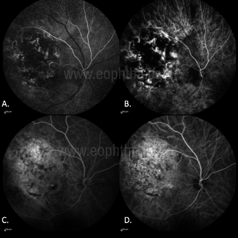
Figure 26 Role of ICGA in choroidal tumors
In Choroidal Melanoma, there is Hypofluroscence - due to blockage of the choroidal blood flow by the pigmentation inherent to the tumor. (Fig 26. A) Hyperfluorescence:Small hyperfluorescent spots may be seen due to lipofuscin deposition at the RPE level. (Fig 26.B) “Double Circulation” pattern consisting of an internal circulation within the lesion and the normal vascularity of the overlying retina. This characteristic is more evident in ICGA (Fig 26.C, D) [14]
References:
- Hayreh SS. The ophthalmic artery, Part III. Branches. Br J Ophthalmol. 1962; 46:212–47.
- Weiter JJ, Ernest JT. Anatomy of the choroidal vasculature. Am J Ophthalmol. 1974; 78:583–90.
- Chan G, Balaratnasingam C, Yu PK, et al. Quantitative morphometry of perifoveal capillary networks in the human retina.Invest Ophthalmol Vis Sci.2012;53(9):5502–14.
- Guyer DR, Schachat AP, Green WR. The choroid: structural considerations. In: Ogden TE, Hinton DR, eds. Retina. 3rd ed. St. Louis: Mosby, Inc; 2001:21–31.
- Wolfe DR: Fluorescein angiography basic science and engineering. Ophthalmology 1986; 93:1617–1620.
- Chao P, Flocks M: The retinal circulation time. Am J Ophthalmol 1958; 46:8–10.
- Saine PJ, Tyler ME, eds: Ophthalmic photography: retinal photography, angiography and electronic imaging. 2nd edn. Boston: Butterworth-Heinemann; 2002:247–248.
- Oosterwijk H: DICOM versus HL7 for modality interfacing. J Digit Imaging 1998; 11(3 Suppl 1):39–41.
- Kabachinski J: DICOM: key concepts-part I. Biomed Instrumen Technol 2005; 39:214–216.
- Kabachinski J: DICOM: key concepts-part II. Biomed Instrumen Technol 2005; 39:292–294.
- Flower RW: Choroidal fluorescent dye filling patterns. A comparison of high-speed indocyanine green and fluorescein angiograms. Int Ophthalmol 1980; 2:143.
- Flower RW, Hochheimer BF: A clinical technique and apparatus for simultaneous angiography of the separate retinal and choroidal circulations. Invest Ophthalmol 1973; 12:248.
- Miyanaga M, Kawaguchi T, Miyata K, Horie S, Mochizuki M, Herbort CP. Indocyanine green angiography findings in initial acute pretreatment Vogt-Koyanagi-Harada disease in Japanese patients. Jpn J Ophthalmol 2010;54:377-382
- Collaborative Ocular Melanoma Study Group. Design and methods of a clinical trial for a rare condition: TheCollaborativeOcularMelanomaStudy.COMS Report No. 3. Control Clin Trials.1993 Oct;14(5):362-91.