

The importance of ultrasound imaging cannot be stressed upon more than the fact that whether you are an anterior segment surgeon, posterior segment surgeon or oculoplastic surgeon, the indications for this modality transcend across all genres of ophthalmology. Many a time, postgraduates find this topic daunting to interpret. This article aims to simplify Ultrasound B-scan in terms of mechanics, terminology, actual procedure, and interpretation without delving deep into the confusing jargon. Some common conditions and their typical presentations will also be touched upon.
For ease of understanding, we will divide this article into the following sections:
- History
- Basic physics and instrumentation
- Terminology
- Indications
- Examination techniques: basic and special
- Features of commonly encountered posterior segment conditions
History
Though the concept of ultrasound waves was known to humans in the 18th century (Lazzaro Spallanzini’s observation on the use of ‘sound whistles’ by bats in darkness), it was applied to ophthalmology only in the 20th century. In 1956, Mundt and Hughes were the first to use A-scan (A stands for amplitude) to detect and evaluate an intraocular tumor.[1] In 1958, Baum and Greenwood developed the first brightness-mode (B) scan in ophthalmology.[2] The technique continued to be refined by multiple personnel in the coming years, which led to the introduction of the first commercially available B-scan equipment by Coleman and associates in the early 1970s.[3] Thereafter, Bronson introduced the portable, contact B-scan machine for ophthalmic use. The need to standardize echographic instrumentation and techniques was eventually felt. Ossoinig [4] extensively worked to this effect by initially developing standardized A-scan and later expanding to B-scan along with developing meticulous examination techniques. Evolution of these led to what is known today as Standardized Echography.[5] The technique continued to expand to include imaging of anterior segment (developed by Pavlin and associates in the early 1990s), color Doppler imaging and digitization of ultrasound in the recent years.
Basic Physics and Instrumentation
Ultrasound waves are acoustic waves that, by definition, have frequencies greater than 20 kiloHertz. ( 1 Hz = 1cycle or oscillation/ sec). Ophthalmic ultrasound usually employs frequencies in the range of 8 to 10 MHz. The following diagram will help to understand the often confusing relationship between frequency, wavelength, depth of penetration into the tissue, and resolution:
|
Higher frequency → Shorter wavelength → Lesser depth of penetration → Better resolution (useful for ophthalmic ultrasound) |
|
Lower frequency → Longer wavelength → Greater depth of penetration → Lesser resolution (useful for abdominal ultrasound) |
How does ultrasound B – scan work?
Before knowing the mechanism of modern-day B-scan machines, it is important to understand the concept of two main terms – Echo and Acoustic impedance
Acoustic impedance – in simple terms, acoustic impedance means the ability of a medium to resist the transmission of ultrasound waves by virtue of its density. Hence it follows that denser the medium slower will be the velocity of sound through it.
Echo – An echo is produced by acoustic interfaces created at the junction of two media that have different acoustic impedances. Greater the acoustic impedance difference between two media, greater is the strength of reflection of the sound wave, i.e., stronger is the echo.
The following diagram will help explain the aforesaid point:
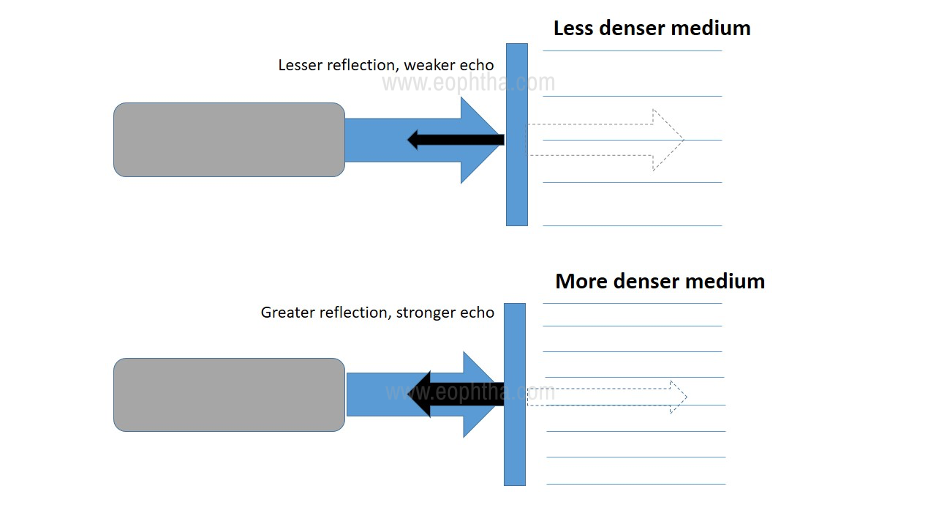
Figure 1: Relation between transmission of sound wave (blue dotted arrow) through two media with different density and the resultant strength of the echo (black arrow)
Having this basic principle in mind, let us understand the components of any B-scan system. Any B-scan equipment has four basic components: A pulser, a transducer, a receiver and a display system. The skeletal flow and connections between these components are illustrated in Figure 2.
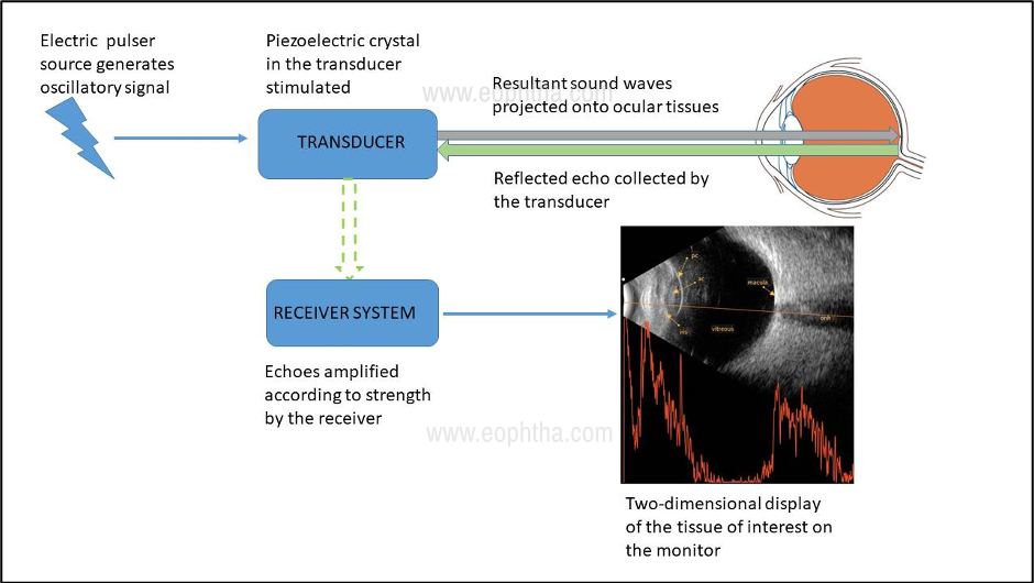
Figure 2: Basic components of any B-scan system and their connections
Terminology
Before proceeding to examination, it is essential to understand some basic terms that will be frequently referred to in the subsequent sections.
Amplification: This forms an important part of the signal processing that occurs before the reflected sound beam is displayed. There are 3 types of amplification, viz., linear, logarithmic, and S-curve.
Gain: This refers to the procedure of increasing or decreasing the amplitude of echoes that are displayed on the monitor
Time-Gain compensation (TGC): This technique is used to enhance the echoes emanating from deeper structures by dampening those from the structures closer to the surface. TGC is typically utilized to study orbital lesions
A-scan: Amplitude display (one-dimensional) in which the returning echoes are displayed as spikes from a set baseline. Greater the strength of the echo, taller the height of the spike.
B-scan: Brightness display (two-dimensional) in which the strength of the echo is displayed as a dot on the screen. The brightness of the dot directly correlated with the strength of the echo.
Indications
An ultrasound B-scan may be ordered in a variety of situations. The most frequently ordered conditions have been illustrated in Table 1.
|
OPAQUE OCULAR MEDIA |
CLEAR OCULAR MEDIA |
INTRAOCULAR FOREIGN BODIES |
ORBITAL LESIONS |
|
Anterior segment: Corneal opacity Hyphema/ hypopyon Miotic pupil Cataract Pupillary/ retroarticular membrane Posterior segment Vitreous hemorrhage/ inflammation |
Anterior segment: Iris lesions Ciliary body lesions Posterior segment Tumors Choroidal detachment: serous vs. hemorrhagic Retinal detachment: rhegmatogenous vs. exudative Optic disc abnormalities Posterior uveitis/ scleritis |
Detection/ localization |
Tumors Orbital foreign bodies Muscle inflammation |
TABLE 1: Indications for ocular ultrasound (Adapted from Bryne SF, Green RL. Ultrasound of the eye and orbit (2nded.).
Examination Techniques
Positioning the patient: while most of the time B-scan is performed with patient reclining or in a supine position, certain ocular conditions mandate sitting position of the patient (for e.g, to demonstrate shifting fluid in exudative retinal detachment, the air bubble in the anterior chamber, etc.) Usually, the scan is performed with the eyelids closed, using a coupling jelly over the probe. In case the eyelids need to be open while performing the scan, the use of topical anesthesia is a must.
Probe orientation: The transducer probe always has a marker, usually a dot, line, or a logo, that is represented superiorly in the two-dimensional B-scan display. This explains the fact that the upper part of the echogram corresponds to the area where the probe marker is placed. For e.g., if the probe marker is placed directed nasally, the nasal quadrant of the globe will be displayed superiorly.
B-scan probe orientations: Three basic probe orientations are employed to evaluate intraocular lesions in B-scan – Axial, Transverse, and Longitudinal.
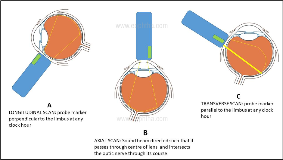
Fig. 3: Schematic representation of various B-scan examination techniques
Longitudinal Scan:The probe is placed such that the marker (and hence the two dimensional sound beam) is perpendicular to the limbus. Hence the beam scans across a single meridian at any given clock hour (Fig.3 A). Thus, it shows the anteroposterior extent of the lesion. The oriented meridian is the one exactly opposite to the meridian in which the probe is placed. For e.g., if the probe placed a 6’o’clock meridian, the picture displayed is the 12’o’clock meridian.
Transverse Scan:The probe is placed such that the marker (and hence the two dimensional sound beam) is parallel to the limbus. (Fig. 3 C)This orientation is useful for demonstrating the lateral extent of a lesion. Depending on the orientation of the probe marker, transverse scans can be horizontal, vertical, or oblique. By convention, in horizontal scans, probe marker is always oriented towards the nose, while it is always oriented above for vertical and oblique scans. The designation of the scan is determined by the meridian that lies in the middle of the scanning section. For e.g., in the right eye, if the probe is held horizontally with its face centered on the 6’o’clock meridian, the superior part of the echogram denotes 3’o’clock meridian, the middle of the echogram denotes 12’o’clock meridian, and the inferior part denotes 9’o’clock meridian.
Axial Scan:In this type, the patient is asked to fix in the primary gaze and the probe is placed on the center of the cornea. The sound beam traverses posterior through the center of the lens, intersecting the optic nerve in its path. (Fig. 3 B) This position is useful to evaluate the macular region, axial length, and position of lesions in relation to the lens and optic nerve. Like transverse scans, axial scans can be performed in the horizontal, vertical, and oblique probe orientations.
Basic Examination
Usually, it is customary to perform transverse scans of the four major quadrants and the longitudinal scans along at least the four major meridians. Eventually, axial scans are performed as needed. The B-scan procedure is performed at both high and low gain settings. Usually, vitreous lesions and gross fundus lesions are better demonstrated in high gain settings. Lower gain settings are helpful to detect relatively flat fundus lesions and topography of large lesions.
Special Examination Techniques
These were devised by Ossoinig to differentiate lesions by analyzing specific acoustic characteristics. These are topographic, quantitative and kinetic echography. The various parameters evaluated under these titles have been enumerated in Table 2.
|
TOPOGRAPHIC |
QUANTITATIVE |
KINETIC |
|
Location |
Reflectivity |
Aftermovement |
|
Extension |
Internal structure |
Vascularity |
|
Shape |
Sound attenuation |
Convection motion |
TABLE 2: Special B-scan examination techniques and the parameters under each category (from Bryne SF, Green RL. Ultrasound of the eye and orbit)
Topographic B-Scan Evaluation
Using the appropriate transverse scans, the gross shape as well as the lateral extent of any lesion can be deduced. The horizontal basal diameter of any three-dimensional lesion such as a tumor can be derived from this scan. Then, using the longitudinal approach, directed perpendicular to the transverse orientation, the anteroposterior extent of the lesion is scanned. This is helpful to derive the apical height and vertical basal diameter of a lesion.
Quantitative B-Scan Evaluation
Three parameters are ascertained under this category:
Reflectivity: this is evaluated by observing the spike height on A-scan vector overlay and signal brightness n B-scan. The types of lesions that canbe assessed with this technique include membranes, bands, opacities, tumors, and foreign bodies. The normal ocular structure causing the highest reflectivity is the sclera (taken to be 100 percent). The reflectivity categories are then decided on a percentage basis as demonstrated in Table 3.
|
CATEGORY |
A-SCAN SPIKE HEIGHT (%) |
|
Very low |
0-5 |
|
Low |
5-40 |
|
Medium |
40-60 |
|
Medium-high |
60-80 |
|
High |
80-100 |
TABLE 3: Reflectivity categories of lesions (from Bryne SF, Green RL. Ultrasound of the eye and orbit)
Internal structure: This property is studied by noting the differences in height and length of the A-scan spikes and differences in echo densities on B-scan. The regular internal structure is represented by little or no variation in A-scan spikes and uniform appearance of echoes on B-scan. This indicated a homogenous internal structure within a lesion. Conversely, the irregular internal structure is represented by significant differences in A-scan spikes and echo densities indicating heterogeneous internal structure.
Sound attenuation: Attenuation of sound occurs when the sound energy is scattered, absorbed, or reflected by any given medium. It is evaluated on both A- and B-scan. In B-scan, it is indicated by a progressive decrease in the strength of echoes, either within or posterior to a lesion. On A-scan, it is demonstrated by a spike decrease is measured by an angle (the Angle kappa) formed by drawing an imaginary line through the lesion peaks with the A-scan baseline. The steeper the angle, the greater is the sound attenuation.
Kinetic B-Scan Evaluation
Kinetic echography is used to dynamically assess the motion of or within a lesion. These are briefly illustrated below.
After movement: it is determined by observing the motion of the lesion echoes following cessation of the eye movement. Depending on the extent of movement, the aftermovement may be classified as good, restricted (or poor), and no aftermovement. This is important in the differentiation between vitreous detachment (good aftermovement) and retinal detachment (restricted aftermovement). Within the lesion, it is important to differentiate between mobile and non-mobile echoes, as this often gives an idea regarding the nature of the substance within the lesion.
Vascularity: This is assessed in tumors. Fast spontaneous motion (i.e., low-amplitude, continuous flickering of internal lesion spikes) is best detected with standardized A-scan. Vascularity is assessed with the probe held stationary and the eye steadily fixating on a target.
Convection motion: This type of movement occurs because of convection currents that occur within blood or cholesterol debris. It can be observed in eyes with longstanding intraocular hemorrhage and certain types of orbital cystic lesions containing cholesterol debris or in Coat’s disease.
Anterior Segment Evaluation:
On direct contact with the lids, cornea, the probe is unable to display echoes for the first few millimeters in front of the probe. This deficiency can be overcome by interposing a fluid column between the probe and the eye. Scleral shells are available for this purpose (immersion technique). Alternatively, the finger of a latex surgical glove can be filled with water (like a water balloon) for the same purpose (stand-off technique). A detailed discussion of these techniques is beyond the scope of this article.
Though the individual discussion of lesions is beyond the scope of this article, a few frequently encountered lesions have been illustrated below. These are important from the point of view of post-graduate examinations as well.
Salient features of classic posterior segment lesions: [6]
Posterior vitreous detachment (PVD)
- Seen as a freely mobile membranous echo.
- Attached to the optic nerve head in incomplete variety. Attachments could be focal or broad, single, or multiple depending on etiology. In complete variety, there is no attachment to the optic nerve head.
- Reflectivity is usually low in age-related PVD. In the case of blood- lined PVD, it may be moderate to high.
- Has good aftermovements.
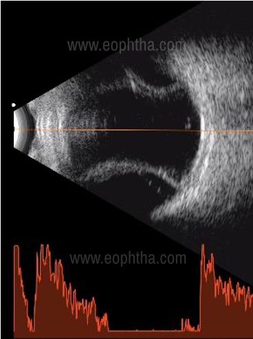
Retinal detachment
Rhegmatogenous retinal detachment
- Usually seen as a membranous echo with limited mobility
- Always attached to the optic nerve head
- Has 100 percent reflectivity
- Restricted aftermovements
- Depending on configuration and chronicity, variations such as cyst formation, closed or open funnel configuration can be observed.
Courtesy: Dr. Anshu Kaushal, Chandigarh
Exudative Retinal Detachment
- Typical features on ultrasound include the presence of smooth bullae, shifting fluid. The presence of shifting fluid can be demonstrated by changing the patient’s position from supine to sitting position. However, bullous rhegmatogenous retinal may also demonstrate shifting fluid sign.
- Since this type is usually associated with tumors or inflammatory conditions, always look for associated signs such as vitreous echoes (suggestive of vitritis/ vitreous seeds), mass lesions, and retinochoroidal thickening.
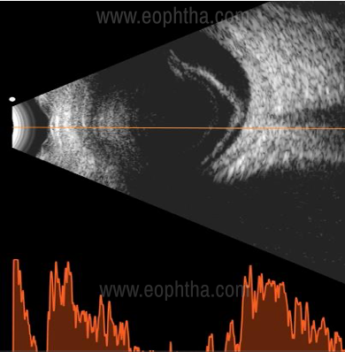
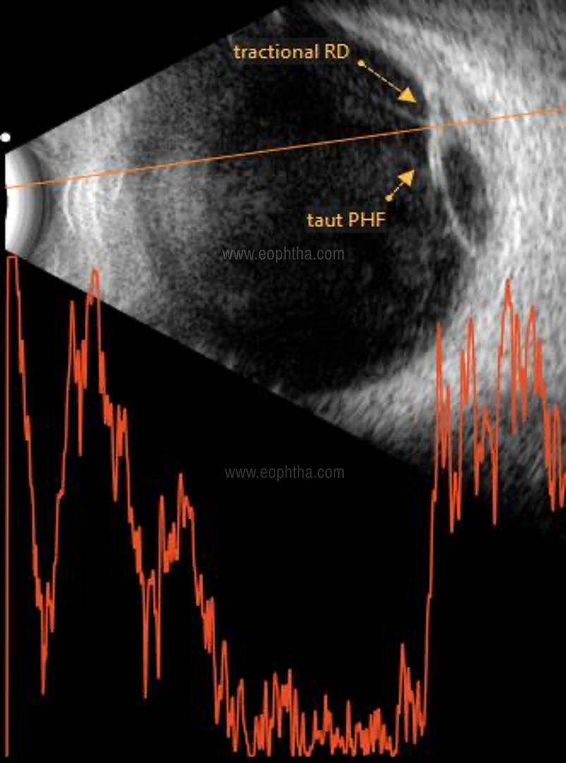
Tractional Retinal Detachment
- Typically seen as a concave membrane (compared to the usually convex configuration of other forms)
- It is usually found in association with diabetic retinopathies, vascular inflammatory conditions, trauma, or endophthalmitis.
- Depending on extent and location, the traction may be broad or focal, peripheral or central, shallow, or highly elevated.
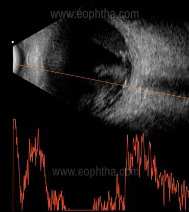
Choroidal detachment
- Usually appears as a smooth, thick, dome-shaped convex membrane. Sometimes, it may have a shallow configuration in the periphery
- It demonstrates a typical double-peak or ‘M’ spike on the A-scan vector, the two peaks representing retina and choroid respectively
- in the case of serous detachment, the space behind the membrane is echolucent.
- In the case of hemorrhagic detachment, the space behind the membrane shows multiple moderate to high reflective dot echoes
- Sometimes, a cord-like linear echo may be seen between the sclera and the choroidal dome – this represents the vortex vein
Courtesy: Dr. Anshu Kaushal, Chandigarh
Vitreous hemorrhage
- This is represented by dot-like, clump-like, or membrane-like mobile echoes in the vitreous cavity.
- A fresh vitreous hemorrhage is echolucent or very low reflective, hence often difficult to pick up. In such a situation, increasing the gain settings is helpful
- A posterior vitreous detachment may or may not be associated
Tumors
Irrespective of the origin of the tumor, certain features to be noted in all are as follows:[6]
- Number, shape, and surface
- Location and layer involved
- Presence or absence of associated RD
- Reflectivity
- Measurements – base: vertical and horizontal, height
- Presence or absence of extrascleral extension, optic nerve extension, orbital involvement
- Vascularity
- Associated inflammatory signs
The tumours important from the PG examination point of view are retinoblastoma and choroidal melanoma. Hence, this article will limit to the discussion of these two tumours.
Retinoblastoma
- Single or multiple lesions seen
- The endophytic variety grows into the vitreous cavity
- Irregular, high internal reflectivity
- Calcium within the tumor is seen as high reflective specks, causing orbital shadowing.
- In the exophytic variant, exudative retinal detachment may be seen overlying the mass, with subretinal echoes signifying subretinal seeds
- The rarely encountered diffuse infiltrating variant manifests as a total retinal detachment with a thick solid mass just behind it. This mass usually has an irregular internal echogenicity and no aftermovements.
Courtesy: Wikipedia
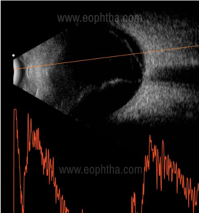
Choroidal melanoma
- Ultrasound B scan is often diagnostic for this tumor
- Classic features include solid dome-shaped or mushroom-shaped configuration due to Bruch’s membrane rupture
- The regular internal structure on B scan
- Low to medium internal reflectivity on A-scan
- Sound attenuation (yellow arrow line) is seen due to its densely homogenous structure. This is manifested as acoustic hollowing on B scan and rapid decay os spikes on A-scan (large angle kappa)
- Choroidal excavation is a feature produced due to contrast between the highly reflective normal choroid and the low to moderate reflectivity of tumour mass
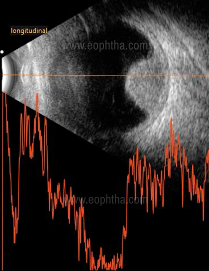
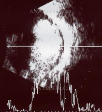
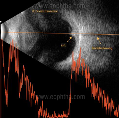
Intraocular foreign body
The features depend on the type of foreign body
Metal and stone being dense, produce high amplitude echoes that often cause backshadowing
Wood and vegetative matter may produce only moderately reflective echoes
Glass IOFB may be difficult to pick up as it produces echoes only when the ultrasound beam is incident perpendicular to its flat surface
To conclude, a working basic knowledge of B scan is essential in the armamentarium of every ophthalmologist. Through this article, we aim to educate the postgraduates and practitioners with the basic principles, examination techniques, and interpretation of B-scan ultrasonography.
References
- Mundt GH Jr., Hughes WF Jr. Ultrasonics in Ocular diagnosis. Am J Ophthalmol 1956;41:488.
- Baum G, Greenwood I. The application of ultrasonic locating techniques to ophthalmology. Ultrasonic slit lamp in the ultrasonic visualization of soft tissues. Arch Ophthalmol 1958;60;263.
- Coleman DJ, Konig WF, Katz L. A hand-operated ultrasound scan system for ophthalmic evaluation.
- Ossoinig KC. Basics of clinical echo-ophthalmolgraphy. IV: Clinical standardization of equipmet and techniques. In: Bock J, Ossoinig KC (eds.): UltrasonographiaMedica. Vienna. Wiener Med Akademie, 1971, p 83.
- Bryne SF, Green RL. Ultrasound of the eye and orbit (2nded.). Jaypee Brothers Medical Publishers, New Delhi.
- Bhende M, Gopal L, et.al. The SankaraNethralaya atlas of Ophthalmic ultrasound (1st ed.) Jaypee Brothers Medical Publishers, New Delhi.